Livegate
Livegate was an attempt animating one my ridiculous zero-abstraction gate-level drawings of a processor by adding a Javascript to the original SVG. In particular, development of logic circuits is possible entirely from within Inkscape.
The source is available on GitHub if you have a strong stomach.
Demo
Because livegate was written while on the train with no internet connection and no knowledge of how Javascript works. As such it is hideously slow and only seems to work in Google Chrome. Click the screenshot below to try it out:

Clicking the input pins on the left will toggle their value. Red wires are high, black wires are low.
Developing Circuits
Circuits are built out of basic components which have input and output wires. These components are defined within inkscape by drawing them and adding metadata to the SVG objects using the "Object Properties" dialogue:
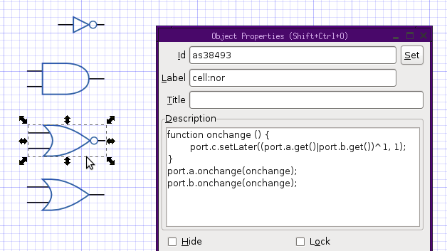
Here the incoming and outgoing wires to the NOR gate are drawn with wires (given
the SVG label a, b and c respectively) along with an appropriate symbol
and grouped together. This group is labelled cell:nor and its description
field is set to a Javascript snippet defining its behaviour. This is done using
a simple Javascript API:
function onchange () {
    port.c.setLater((port.a.get()|port.b.get())^1, 1);
}
port.a.onchange(onchange);
port.b.onchange(onchange);
Which approximately does the same as the following Verilog:
wire a;
wire b;
reg  c;

always @(a, b)
    c = ~(a|b);
Because this is just Javascript, complex behaviour can be defined (including things like clock sources, memories and even the clickable pins used in the demo above).
The components can be cloned to create as many instances of them as required and built up into complex devices in their own right. They can be connected by drawing (completely normal) lines using standard drawing tools.
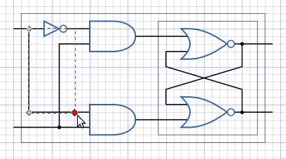
These blocks can, of course, be duplicated and reused in larger circuits allowing larger systems to be defined such as in the flip-flop demo.
Caveats
As mentioned above, this project was done on the train with no Javascript or SVG references (nor experience on my part) and so the code is a little dodgy, for example the demo eats memory and quickly starts to lag horribly.
Though this code could easily be improved substantially, it sadly would be impossible to scale it to a full system. The sheer size of the static SVG of the STUMP CPU brings Chrome to its knees, adding interactivity would simply not be practical. Alas, back to the drawing board for animating big machines but still, a fun proof of concept for designing VLSI in Inkscape!